Filter
codepen practice pageoverview
SVG filters are extremely powerful, and allow you to apply photoshop level visual effects to SVG graphics.
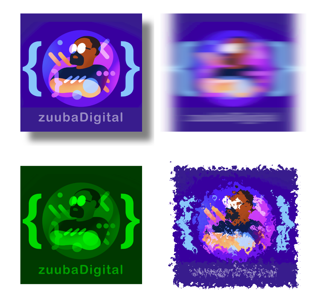
Because of the power and potential complexity of filters, it’s possible to devote an entire course to filters alone. In this class I’ll provide a basic overview of filters, and how they can be applied to SVGs or other HTML elements.
the filter element
Filters are reusable elements, like gradients and patterns, and are generally defined in the <defs> section. Note: filters aren’t rendered directly, so they don’t have to live in <defs>, but it makes for cleaner, more readable code if all reusable elements are kept in the same place.
Filters are defined with the <filter> element. Each filter has an id, so that it can be applied to a visual element.
<filter id="drop_shadow">...
1
2
3
4
5
6
7
8
<defs>
   <filter id="drop_shadow">
       <!-- filter code goes here -->
   </filter>
</defs>

<image filter="url(#drop_shadow)" ...>
</image>
filter primitives
Each filter element contains one or more filter primitives. Each filter primitive performs a single graphical operation. In the example above we uses the feDropShadow filter primitive to create the drop shadow.
We'll explain all the filter primitive attributes later on in the lesson.
1
2
3
4
5
<filter id="shadow">
    <feDropShadow...>
        // filter primitive code goes here..."
    </feDropShadow>
</filter>
In the next we use two filter primitives, feTurbulence and feDisplacementMap to create a distortion effect.
1
2
3
4
<filter id="turb-displace-filter">
    <feTurbulence ... />
    <feDisplacementMap ... />
</filter>
In this course, we’ll learn about 5 different filter primitives:
- feDropShadow
- feGaussianBlur
- feColorMatrix
- feTurbulence
- feDisplacementMap
feDropShadow
attributes
- dx: the horizontal offset of the shadow
- dy: the vertical offset of the shadow
- stdDeviation: sets the amount of the “blurriness” of the shadow. The higher the number, the softer the edge of the shadow
- flood-color: the color of the shadow
- flood-opacity: the opacity of the shadow at its most opaque point.
1
2
3
4
5
6
7
<filter id="shadow">
    <feDropShadow
        dx="15" dy="15"
        stdDeviation="5"
        flood-color="black"
        flood-opacity=".5" />
</filter>
feGaussianBlur
attributes
- stdDeviation: sets the amount of the “blurriness” on both the x and y axis.
You can set different values for both the x and y axis by using two numbers. In the example below we'll only blur along the x axis.
1
2
3
<filter id="blur-filter">
    <feGaussianBlur stdDeviation="10 0" />
</filter>
feColorMatrix
The feColorMatrix allows you to manipulate the colors of a graphical item by using a matrix to transform each pixel’s color channel (Red Green Blue Alpha, or RGBA for short) to a new color value.
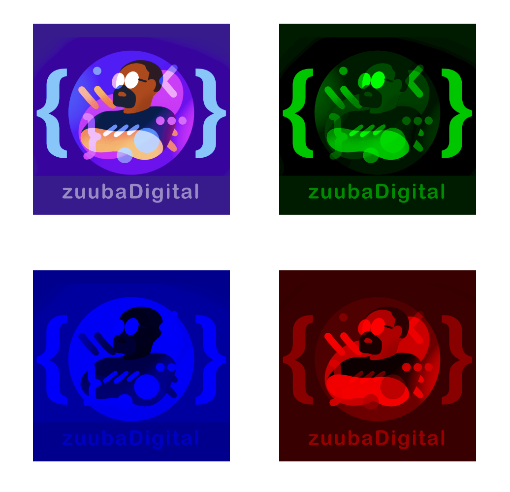
We’re going to discuss three color matrix types:
- saturation (feColorMatrix type="saturate" )
- hue-rotation (feColorMatrix type="rotation")
- matrix (feColorMatrix type="matrix")
feColorMatrix type="saturate"
The “saturate” colorMatrix type changes the color saturation of the graphic. A saturation value of “1” is the default value, and leaves the image unchanged.
1
2
3
<filter id="color-matrix">
    <feColorMatrix type="saturate" values="1" />
</filter>
A saturation value higher than 1 increases the color saturation of the image. Here’s what the same image looks like with a color saturation value=”2”
1
2
3
<filter id="color-matrix">
    <feColorMatrix type="saturate" values="2" />
</filter>
A saturation value less than 1 decreases the color. To make a grayscale image, set the value=”0”
1
2
3
<filter id="color-matrix">
    <feColorMatrix type="saturate" values="0" />
</filter>
feColorMatrix type="hueRotate"
The hueRotate type is used to shift an object’s hue. Values are in degrees, and can be from 0 to 360.
1
2
3
<filter id="color-matrix">
    <feColorMatrix type="hueRotate" values="60" />
</filter>
1
2
3
<filter id="color-matrix">
<feColorMatrix type="hueRotate" values="300" />
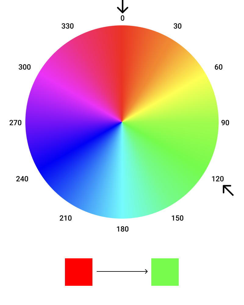
</filter>The hueRotate type utilizes a color wheel to change a pixels hue. For example, if the pixel is red, and the hueRotate value is 120 degrees, the red pixel’s color will shift to green.
feColorMatrix type="matrix"
The matrix color uses a matrix math to change each pixel's color value.
A matrix looks something like this:
R G B A shift
new R = r1 r2 r3 r4 r5
new G = g1 g2 g3 g4 g5
new B = b1 b2 b3 b4 b5
new A = a1 a2 a3 a4 a5
And it can be read like this:
new R = old R*r1 + old G*r2 + old B*r3 + old A*r4 + shift
new G = old R*g1 + old G*g2 + old B*g3 + old A*g4 + shift
new B = old R*b1 + old G*b2 + old B*b3 + old A*b4 + shift
new A = old R*a1 + old G*a2 + old B*a3 + old A*a4 + shift
Let's look at an example. Lets look at a matrix that won't change any of the values.
R G B A shift
new R = 1 0 0 0 0
new G = 0 1 0 0 0
new B = 1 0 1 0 0
new A = 1 0 0 1 0
which can be read like this:
new R = old R*1 + old G*0 + old B*0 + old A*0 + 0
new G = old R*0 + old G*0 + old B*0 + old A*0 + 0
new B = old R*0 + old G*0 + old B*1 + old A*0 + 0
new A = old R*0 + old G*0 + old B*0 + old A*1 + 0
Let's simplify the equation:
new R = old R + 0 + 0 + 0 + 0
new G = 0 + old G + 0 + 0 + 0
new B = 0 + 0 + old B + 0 + 0
new A = 0 + 0 + 0 + old A + 0
and the result:
new R = old R
new G = old G
new B = old B
new A = old A
Suppose we only want to see the red channel for each pixel. We’d use the matrix below.
1 0 0 0 0
0 0 0 0 0
0 0 0 0 0
0 0 0 1 0
Let's see what happens when we take our pixel RGB value of 110, 50, 180 with and alpha of 1 and matrix multiply it:
new R = 110*1 + 50*0 + 180*0 + 1*0 + 0
new G = 110*0 + 180*0 + 180*0 + 1*0 + 0
new B = 110*0 + 180*0 + 180*0 + 1*0 + 0
new A = 110*0 + 180*0 + 180*0 + 1*1 + 0
110 = 110 + 0 + 0 + 0 + 0
0 = 0 + 0 + 0 + 0 + 0
0 = 0 + 0 + 0 + 0 + 0
1 = 0 + 0 + 0 + 1 + 0
Let's take a look at what happens to our image when we apply the "red channel only" matrix filter:
The shift value is the amount you want to shift the color of every pixel in the image. For example, we're shifting the value of every pixel to the maximum "R" value. So a pixel with an rgb value of rgb(100, 25, 100) would now be rgb(255, 25, 100)
R G B A shift
new R = 1 0 0 0 1
new G = 0 1 0 0 0
new B = 1 0 1 0 0
new A = 1 0 0 1 0
Here we're shifting the value of every pixel to the maximum green value.
R G B A shift
new R = 1 0 0 0 0
new G = 0 1 0 0 1
new B = 1 0 1 0 0
new A = 1 0 0 1 0
Distortion effect with feTurbulence and feColorMatrix
The distortion effect requires chaining together two separate filter primitives: feTurbulence and feDisplacementMap.
feTurbulence
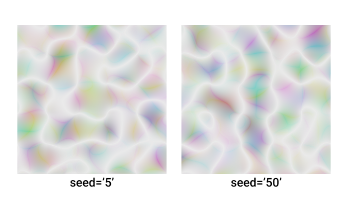
feTurbulence is used to create random, fluctuating noise patterns, and can be used to generate textures like clouds or blobs.
1
2
3
4
5
<filter id="turbulence">
<feTurbulence baseFrequency=".01" numOctaves="1" seed="5"/>
</filter>
<rect filter="url(#turbulence)" ... />The noise is generated under the hood by the Perlin Turbulence Function (the inner workings of which are well beyond the scope of this course), and can be altered using the following attributes, which are parameters for the function:
- baseFrequency
- numOctaves
- seed
- result
The Perlin Turbulence Function function will generate the same image every time, given the same baseFrequency, numOctaves and seed values. The best way to learn how affect the nature of the generated image is through experimentation.
feDisplacementMap
A displacement map uses the pixels of one image as a map to shift the pixels of another image. We’ll use the result of the feTurbulence filter and apply it, using the displacement map filter, to an image to create the distortion effect.
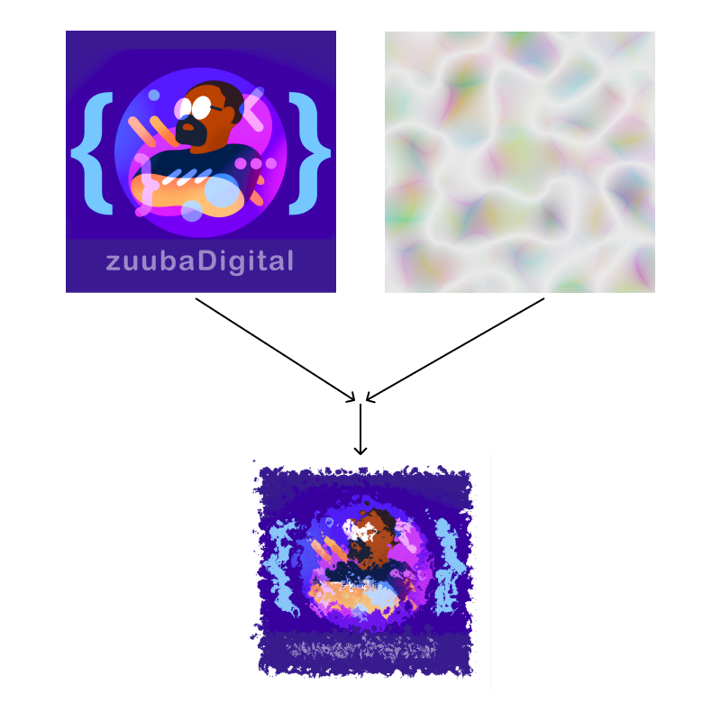
In order to use the result of the feTurbulence filter, you have assign it a name using the result attribute. You can think of it as a variable name, which allows you to pass it as a parameter to the feDisplacementMap filter. We'll just call the result "my-turbulence"
<feTurbulence ... result="my-turbulence"
1
2
3
4
5
6
7
<filter id="turb-displace-filter">
<feTurbulence
type="turbulence"
baseFrequency="0.05"
numOctaves="5"
result="my-turbulence" />
</filter>feDisplacementMap has four attributes that we'll need to set
- in
- in2
- xChannelSelector
- yChannelSelector
- scale
The in and in2 attributes are used to identify the inputs to feDisplacementMap. The feTurbulence result is passed via its result to "in2", while "in" is used to identify what the displacement map is applied to. “SourceGraphic” is simply the element to which the filter is being applied.
<feDisplacementMap in="SourceGraphic" in2="turbulence" ...
The xChannelSelector is used to define what color channel from in2 is used to displace the in pixels along the x-axis, and the yChannelSelector is used to define what color channel from in2 is used to displace the in pixels along the y-axis. They can be set to one of three values: "R" "G" or "B". There is no "right or wrong" value here - they will each produce different results based upon the color composition of the image used.
<feDisplacementMap ...
xChannelSelector="R" yChannelSelector="G" ...
Finally, the scale is the amount of displacement. the higher the number, the greater the displacement. Setting the scale to "0" would result in the displacement map having zero effect on the image.
<feDisplacementMap ...
scale="30" ...
1
2
3
4
5
6
7
8
9
10
11
12
13
14
15
16
17
18
19
20
<defs>
    <filter id="turb-displace-filter">
        <feTurbulence
            type="turbulence"
            baseFrequency="0.05"
            numOctaves="5"
            seed="0"
            result="turbulence"  />

        <feDisplacementMap
            in="SourceGraphic"
            in2="turbulence"
            xChannelSelector="R"
            yChannelSelector="G"
            scale="30" />
    </filter>
</defs>

<image
    filter="url(#turb-displace-filter)" ...>
The filter region
Filters by default are 120% of the width and height of the bounding box of the graphic being filtered. If the filter extends beyond this region, you’ll notice that the effect gets cut off.
You can redefine the filter region using the x, y, width and height filter attributes.
The default value for x and y is -10%, and the default value for width and height is 120%. Let's change these values to get a larger filter region.
1
2
3
4
5
6
<defs>
    <filter x="-20%" y="-20%"
    width="140%" height="140%"
    id="big_shadow">
    <feDropShadow ... />
</filter>